FAQ - Optimizer4D
Physical basics
Process optimization and crack detection using QASS Optimizer4D both work on the basis analysing structure-borne sound. Optimizer4D displays the production process in a three-dimensional diagram with the axes time (x), frequency (z), and amplitude (y).
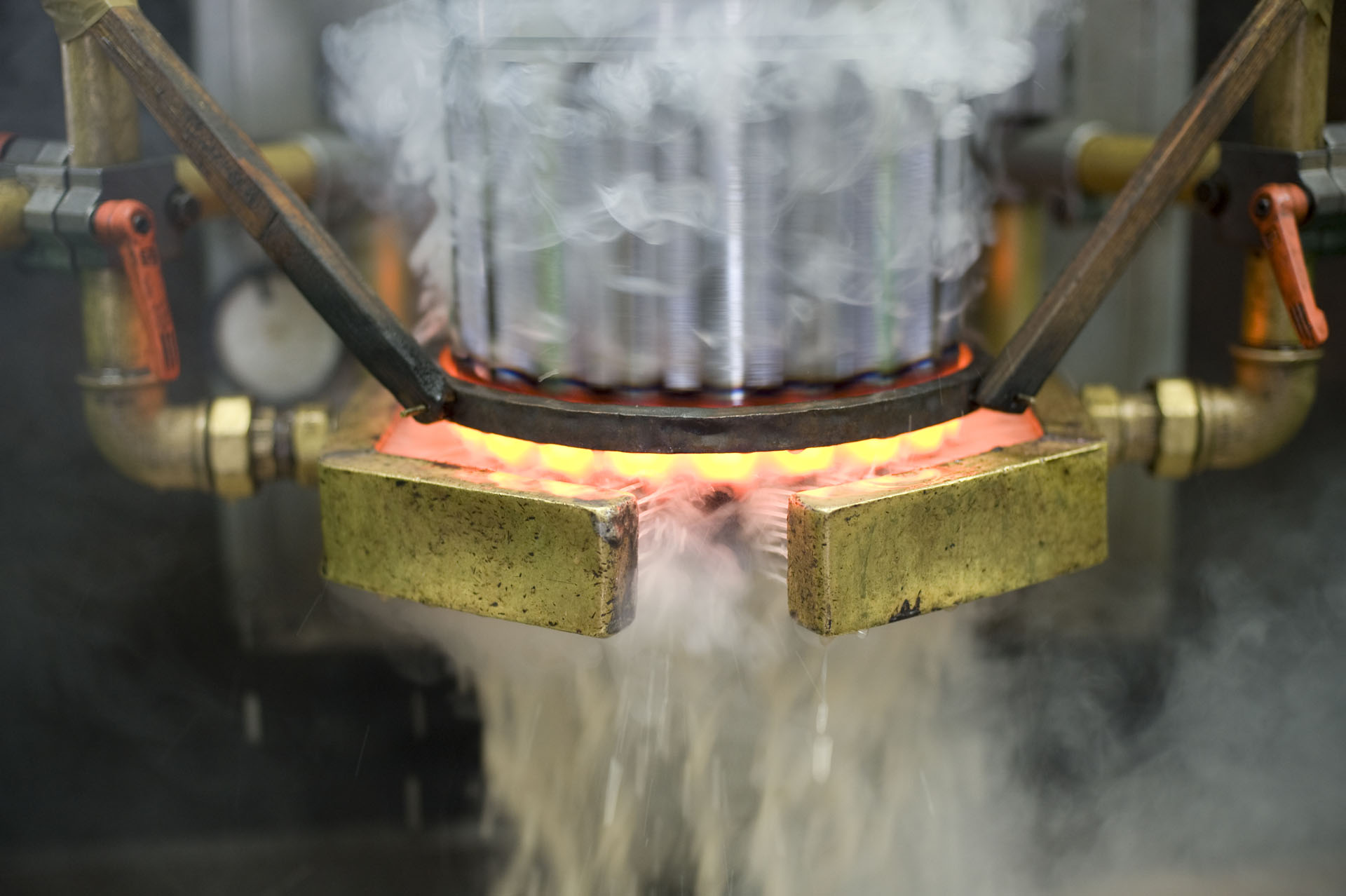
The measuring device has to be adjusted to the respective production process. Cracks are easily and automatically detected in the 3D diagram due to their characteristic form. Furthermore, the qualification of other process parameters is possible. To achieve this it is recommended to reset the device to the desired condition of the process. Deviations can later be detected automatically with crack detection or pattern recognition. The set-up of the desired condition is required. Example: An inductor at an induction hardening machine is supposed to be monitored. The inductor delivers a steady frequency band at roughly 32 kHz. When there are deviations in frequency or amplitude, the Optimizer4D gives a warning signal as soon as the threshold values are exceeded or fall below the limit. This operating principle can be transferred to many different industrial production processes.
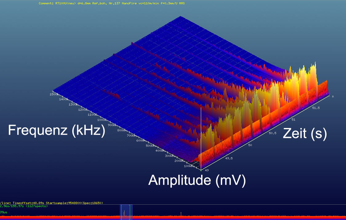
Three-dimensional image of the HFIM signals on the axes time (right), frequency (left) and amplitude (vertically).
Optimizer4D shows the high-frequency-impulse-measuring data in a three-dimensional diagram with the axes time (x), frequency (z), and amplitude (y). An advanced analysis software makes the differentiation of signals possible – it gathers the data from the acoustic emission sensor and edits it using fast Fourier transformation, amongst others. This frequency distinction makes the signals of each aggregate visible – non-destructive, automatic, in-process.
This is a highly individual procedure, since every machine and every process is different. The finer the textures in component and material, the faster the pressure waves follow each other and the higher the maximum vibration frequencies.
Axis inscription of the Optimizer4D cascade diagram.
The sensors use the piezo-electric effect. impulse waves cause pressure building inside the sensor, which is then measured by the Optimizer. This effect can be reversed – when the sensor is charged, it can send out an impulse. To guarantee an optimal connection and thus optimally evaluate the acoustic emission signals, it is suggested to screw the sensor on to the machine (M5 thread). The closer the sensor is to the source of the impulse, the better. Coupling the sensor using a magnet also is possible but screwing it on delivers better results.
In the 3D diagram of the Optimizer crack signals always show in the form of a broadband, high-frequency signal that starts abruptly and then calmly decreases. It is typically not bound to a certain frequency area and differs from machine noise, because it is moving across the time axis. It also has a sharp beginning and it expands across the bigger part of the frequency spectrum starting in the audible area of under 20 kHz and rising to the extreme high-frequency area of 1.5 MHz and beyond. The duration of a typical crack signal is rarely longer than 20 ms.
Rarely. Generally, crack signals clearly stand out from production-related noise. Frequency areas can also be masked and filtered out of the measuring results.
In tool monitoring it is important that the signals of the respective tool can be distinguished from the machine noise in a matter of time or area, which is possible in most cases. A test measurement will shed light on this.
Echoes and feedbacks are always part of the acoustic emission measuring and the process characteristics. Either they are there or not. For the measurement and its evaluation using HFIM they are irrelevant, because either way a typical display of the process will be generated.
Conventional structure-borne sound measuring techniques usually work with a two-dimensional display of time (x-axis) and amplitude (y-axis). Optimizer4D also measures the frequency. During bending and straightening processes for example, a preset area of 512 discrete frequencies is being measured. This measurement area can be freely filtered and adjusted, the background noise and process noise of the machine can be suppressed. Cracks in the material have a characteristic signal and can be recognized automatically. It is also possible to recognize patterns.
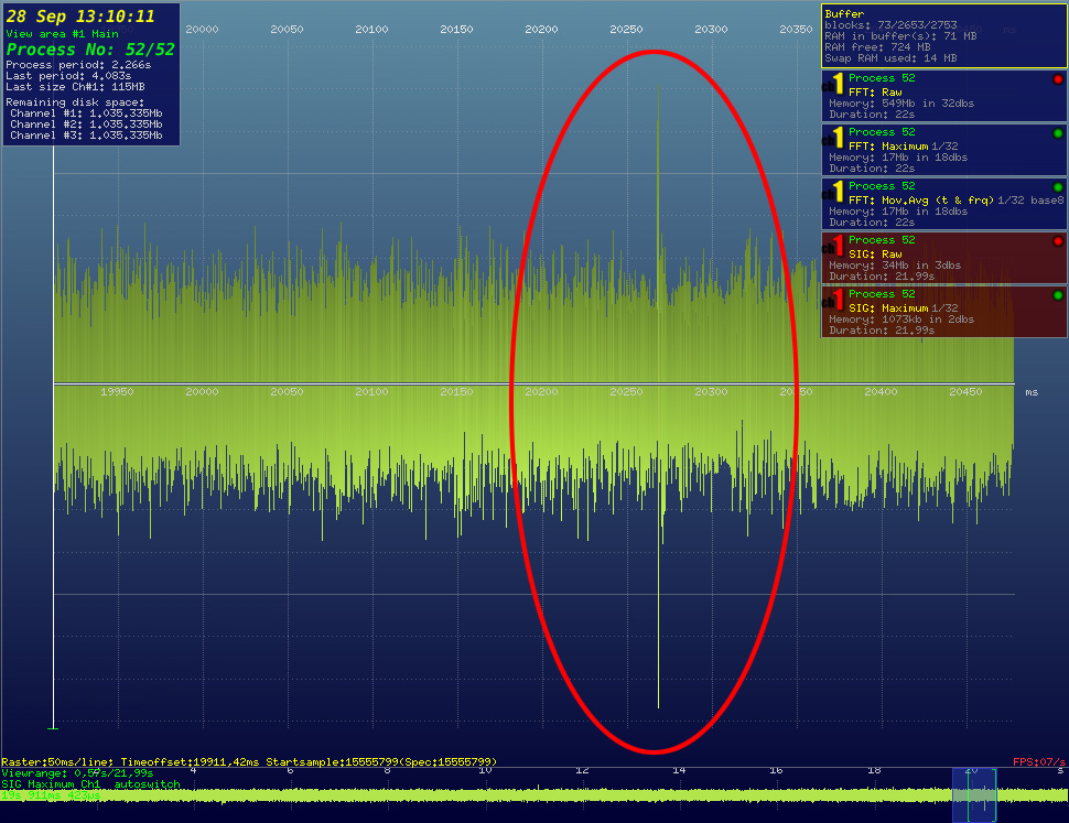
This conventional two-dimensional image of acoustic emission signals can barely be evaluated automatically. The signal-to-noise ratio is extremely small. The marked signal of a cracked disappears completely within the noise.
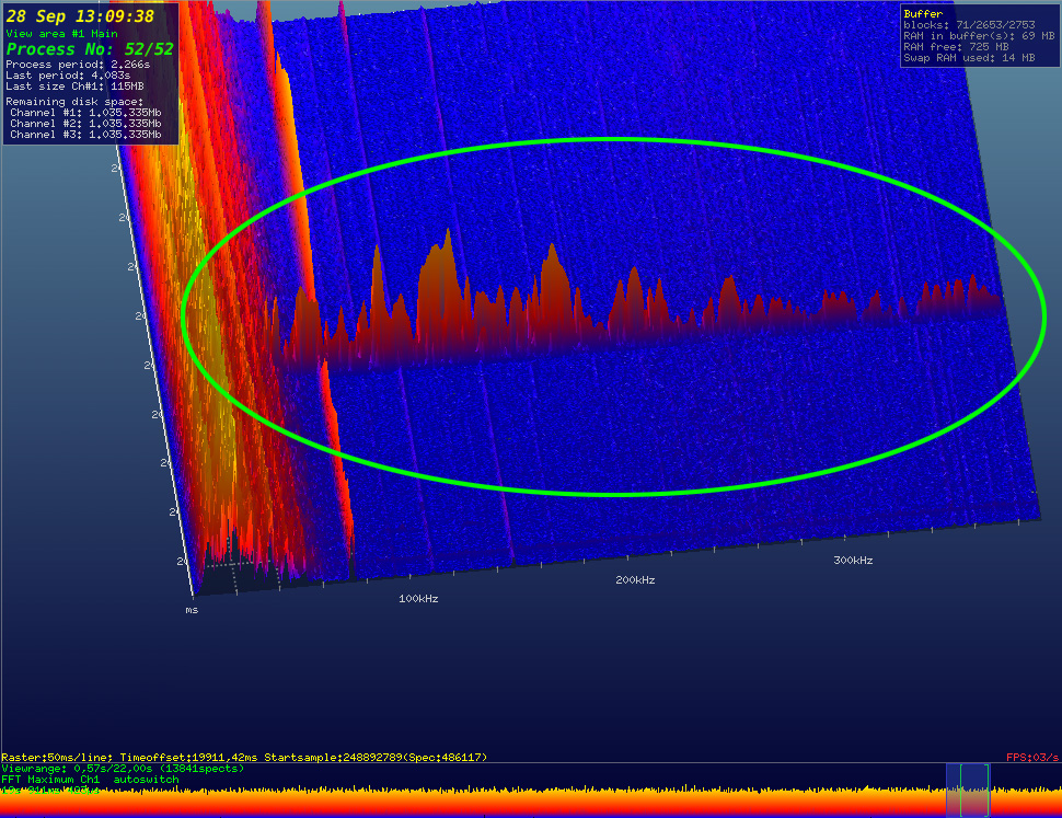
This image shows the same signal as the two-dimensional diagram above. The difference: The Optimizer4D shows the acoustic emission signals on three instead of two axes. Noticeable is the particularly increased accuracy, the marked signal is clearly visible. An automated crack detection is easy and safe.
Application fields
No. The measuring device detects cracks and process parameters in real time, i. e. during their occurrence.
A component can, therefore, not be tested downstream, i. e. after its processing. It can only be done during the production process.
It is possible under certain circumstances. To detect cracks reliably a structure-borne sound sensor has to be coupled to the process and be integrated into the component force-fitly. The closer the sensor is to the component, the better the measurement results will be. If a component is annealed at a different location than the induction hardening machine, which the Optimizer is monitoring, the annealing machine has to be connected to a sensor as well.
The stronger the connection between the sensor and the holder or the component, the better the structure-borne sound signals are transferred. Whether the sheer weight of a component lying on a holder (while cooling down) is enough to transfer signals reliably to the sensor screwed to that holder, depends on many factors. At the same time, it is important to suppress noise to a minimum, especially during the cool down phase a lot of noise is generated, which can be misinterpreted as cracks.
In case of doubt, a test measuring ensures clarity.
Inductive hardening
It depends. Often the impulse emissions of fluids are too small to distinguish them from the process noise of a machine without a doubt. There are, however, machines where the flow of a fluid is clearly visible and emerges as a frequency band. If that is the case, an automated monitoring can be realized. It generally applies that: The moment a parameter inside the process is changed, the measuring results change too. When a lubricating film tears off, for example, it is clearly visible. Similar can be said when the cooling system fails. The perfect answer for this is, however, difficult and depends on each individual case.
QASS, therefore, recommends a test measuring to clarify details.
The Optimizer4D can continue. For successful crack detection and tool monitoring it is advantageous to teach the changed parameters before the process and tell the Optimizer4D in-process to react to changes. Crack signals differ greatly from the other process sounds. Optimizer4D can additionally monitor different parameters in a process. It can monitor a predetermined frequency band or the condition of a tool and afterwards communicate with the machine (via e. g. SPC).
Many different combinations of components, materials, and production processes can be monitored by Optimizer4D. The automated detection of cracks, however, requires an exact parametrisation to the process and component. When the component changes it is possible that the crack signal changes as well. Each component has to be parametrized in the Optimizer once.
The measuring device can store hundreds of components; the list of crack signal parameters is only limited by the disc space. It is possible to switch the device to a different, predetermined parameter during the process by using SPC, for example. Therewith changing components or process parameters can be monitored given that they were entered before the production process started.
One optimizer can, basically, only carry out one measurement at a time. The measuring system can receive signals from up to 4 data channels at once. These channels can be used independently from each other and can each be used to regulated and control. However, all data channels start simultaneously at the beginning of a measurement. If the device detects a crack on one of the channels, for example, it can be evaluated separately from the other channels and can then be used to regulate or control the production machine. Prerequisite for the use of the Optimizer at multiple machines is that the machines are clocked with each other in the aspects of starting and ending times of the measurement.
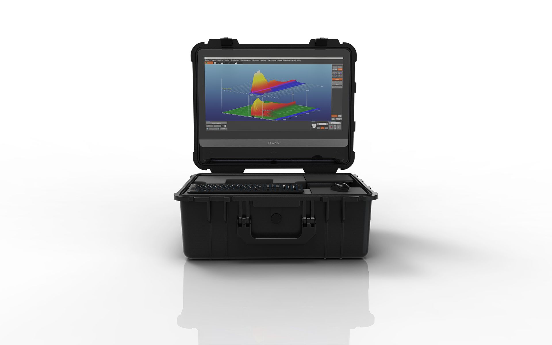
Yes, there are different cases for the Optimizer, which also include different mobile versions (e.g. in a mobile case) or a box for uses as a single unit at manual presses. One variant is the robust transport case QASE, included is a touch screen monitor. The standard variant is for mounting into a control cabinet with a connection to the machine controls (e. g. SPC).
A UPS is a basic part of the Optimizer4D. The UPS uses supercapacitors (“Supercaps”) and provides enough power to shut down the system safely in case of a power failure.
The device uses an uninterrupted power supply (UPS) and thusly no problems should occur due to a power failure. In case of frequent starts and shutdowns data errors and data loss are possible.
Test measuring
The test measurement at a machine takes a minimum of three hours. Added is the work time for preparations, like exchange of details about the machine. It is necessary to formulate an objective before the start of the test measurement. It would be also useful if the components manufactured during the test measurement are made available to QASS for further analyses with other testing methods. QASS will do the test measurement with regards to the production process but a certain time to adjust the measuring device to the production machine should be calculated in.
The better the testing environment, the more revealing will be the results. The support by a capable machine operator is a requirement.
A test measurement has to be prepared. In the past it has proven useful when QASS technicians were able to prepare themselves for the machine and production process, which is to be tested. Therefore, we ask for as much information about the machine and process as possible. Basically it is always about the right coupling of the sensor. These have to be placed as close to the component as possible.
To prevent pseudo waste, we suggest to mark and gather the tested components and possibly use a downstream testing method on them to be able to interpret the signals of the Optimizer correctly. Once the interpretation is done the downstream testing usually becomes obsolete.
The more components are tested, the better will be the results. There is no explicit amount, it also depends on the components and the process. Experience has shown that it is best to reserve a certain amount of components for the test measurement.
Measuring chain/Measuring sensitivity
Sensor (optional: Ceramics adapter for electrical decoupling) – different mountings (screws, magnets) – preamplifier – main device Optimizer4D – measuring and evaluation software Analyzer 4D.
The sampling rate is 50 MHz, in the frequency-time-amplitude diagram 25.000 spectral lines per second are calculated and displayed in real time. Optimizer4D is a measuring computer, which is based on a highly-productive Linux-system and is equipped with special, customised measuring hardware. The measuring hardware is constructed to convert high-frequency, ultra-sonic signals of up to 25 MHz. Typically, breaking a pencil’s lead near the sensor (the so called “Nielsen-Test” according to DIN EN 1330-9) leads to a clearly visible amplitude on the screen with the normal form of a crack signal.
- 50 MHz sampling rate for up to 4 measuring channels
- Storage of the measuring data (up to 80 MB/s and channel) on hard drives (amounting up to 8 Terabyte storage volume, enough for about hours if measuring)
- 24V I/O-unit for direct communication with the machine (enables automated process control)
- Extensive software with many analysis and statistics tools
That also depends on the noise generated by the process, which can complicate the crack detection of very small cracks when the generated noise is very broad banded and loud. Typically, the “Nielsen-Test” (a pencil’s lead is broken near the component, which then shows a similar signal pattern to cracks on the monitor [abrupt start, high frequency and broad banded]) works if the sensor is coupled well.
Prerequisite for this is that the sensor is force-fitly coupled as close to the component as possible, without cushioning structures like bearings and gears between sensor and component.
.
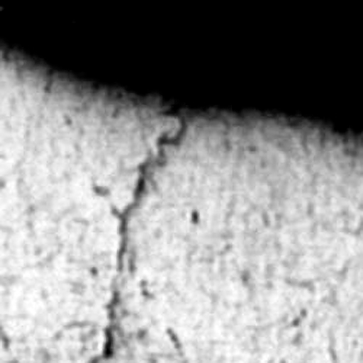
A crack in a work piece, detected by the Optimizer4D.
Often, but now always. It is possible for cracks to close at the surface of a component, while it is still being worked. These cracks, while still there, are no longer visible and cannot be seen anymore by magnetic particle inspections or eddy current tests. Optimizer4D is able to detect these cracks the moment they occur.
The measuring system gives out a signal immediately after the crack is detected and during the deformation, but after 100 ms, after the measuring window ends, at the latest.
Parameterization/Operation
The Optimizer4D software allows a distinction of measured crack signals into micro cracks, cracks, and breaks. These three states can be clearly parametrized. Basically, the Optimizer4D’s automatic crack detection is provided using a clearly definable frequency band in combination with a clearly definable period of time. Additionally, it is possible to define a noise level which leads to only energy levels higher than the defined level being consider for the analysis. The automatic crack detection can be started and ended by external trigger signals like SPC machine control.
The terms crack, micro crack, and break are labels for different crack-parameters, i. e. for different definitions of frequency band, time period, and noise level. The machine is not able to recognize cracks or breaks by itself, it has to be adjusted to each production process. .
Measured data from processes are saved. This enables you to replay the measured data again and again, like a film made of structure-borne sound signals. The crack parametrization can be applied to these recordings and can be adjusted to set them to the required parameter area.
The measuring system counts the crack, micro crack, and break events and displays a warning on the screen and/or the I/O-port if the number of events exceeds a threshold value.
Via the interface Optimizer4D-SPC. Optimizer4D has 16 to 24 input ports, configurable with software parameters; it also has 8 to 16 output ports they are configurable with the software, too. A Profibus connection is optional.
Yes. You can run the measuring for a previously set period. It is also possible to stop the measuring using a signal from the I/O-port or stopping it manually. There is one other option: The crack detection can be stopped for every single channel, so that the measuring continues, but the crack detection only works on the enabled channels. The crack detection can be activated or deactivated using the I/O-port or a timer.
Yes. You can parametrize different starting times for every port.
You get optimal testing conditions when the machine is idle. If the machine’s working noise is low, the self-test should work even with the machine active.
One test takes less than 100 ms. If an error occurs, the self-test can be repeated to save the measuring. This prolongs the time accordingly. If you repeat the self-test twice, the period is still under 300 ms. More than two repeats are unnecessary.
Yes, even over a few days’ time. You have to consider this when ordering the system, since we need to install extra memory space.
Data storage
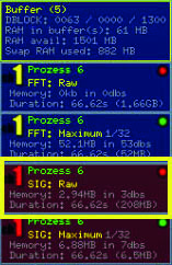
Basically, lossless raw data is saved in real time. This data is called “Buffer”. This buffer can be edited in different ways later, to fade out noise signals or augment weak signals.
The Fast-Fourier-Transformation is used as a standard to display the data on the axes time(x), frequency(z), and amplitude(y). The transformation always works non-destructively and does not influence the original data. The measuring data is saved in a specially designed format on the memory of the system. It is possible to export individual buffers into a csv-format (character separated values) and then edit it with an external tool (e.g. Microsoft Excel)
Of course. This is very easy to do with our archive system. Prices and delivery time on request.
Yes. It is possible to assign different user groups with different access authorizations. Nearly every option in the settings (function, parameter) can be configured individually. On the one hand you can have the machine operator with access to only the most basic functions to see the information without access to the system. On the other hand, you can assign a highly authorized user with access to every setting. This user group system uses passwords as protection.
It is, generally, possible to delete the raw data and only save compressed data, which is not as precise as the raw data. Using compressed data saved up to 32 times more memory storage capacity.
Support/Service/Purchase procedure
Generally speaking: The sensors and cables are wearing parts. The life expectancy strongly depends on the application field.
Sensors and cables used in processes where they frequently move or are exposed to other factors, like cooling water, have to be exchanged earlier than sensors not under these influences. Usually, sensors and cables work properly for more than two years. We recommend to keep these wearing parts in stock. Furthermore, we recommend an annual calibration which is also important to adjust process parameters that might have changed.
The annual calibration ensures that the system measures properly. We recommend an annual calibration and remind our clients three months before it is due.
The QASS head office in Germany ensures a worldwide service to all clients. Included are training, process accompaniment, and repairs. These services are provided either by our German technicians or our distribution partners.
Yes. Our head office in Wetter/Ruhr offers a free telephone number to contact service technicians on weekdays during the usual office hours. We offer this service in German and English. We are also able to give you support in Spanish, French, Portuguese and Arabic.
Urgent services are provided by QASS as soon as possible. For common service calls we have a lead time of approximately four weeks.
Usually, QASS has the parameters and client settings of all clients’ measuring systems due to the annual calibration. This enables us to send a replacement device with the correct parameters at a charge. Delivery time without customs is usually 24 hours. As soon as the client receives the device he has to send the broken one to QASS. It is a good alternative to keep a replacement device in stock.
Im Allgemeinen ist eine Remote-Unterstützung per Team Viewer möglich; dazu muss der Netzwerkzugriff über eine Standard-Ethernet-Verbindung konfiguriert werden. Der Optimizer muss eine Verbindung in das Internet erhalten. Dazu müssen Gateway- und DNS-Daten in Optimizer4D eingegeben werden. Ist Optimizer4D an das Internet angeschlossen, kann auf dem Optimizer der Firefox Internet-Browser ausgeführt werden (der bereits installiert ist). Team Viewer kann im Anschluss installiert werden (www.teamviewer.com; „Download rpm“; Details zu der Prozedur können Sie bei uns erfragen).
There are other, easier options to get remote support. We suggest to configure the router with a so-called Port Forwarding on SSH Port (22). Generally, we don’t support a wireless communication for Optimizer4D. In some cases this is possible, we had good results using the DLink DWR 512 router, for example.
Yes, Monday to Friday between 8.30 a.m. and 4.30 p.m. German time. Usually, the support is free within the first year. The costs for support afterwards are individual.
Six to eight weeks.
Preise sind auf Anfrage erhältlich unter info@qass.net oder per
telefonischer Anfrage unter +49 (02335) 80200. Die Zahlungsmodalitäten
werden individuell mit jedem Interessenten vereinbart und auf jeden
Kunden maßgeschneidert.
Yes. Loan costs depend on the application field and the QASS service technician’s efforts and thus are fixed individually.
QASS offers a detailed Optimizer4D manual. We offer additional material at our in-depth training courses.
Yes. A maintenance agreement generally offers price advantages concerning the traveling costs for a calibration. The more clients QASS has in a certain region, the better the possibility to split the traveling costs.
The cables are wearing parts. The maintenance interval depends on the working environment of the cables. Sensors are, also, wearing parts and have to be calibrated annually. Furthermore, QASS recommends to exchange the hard drive every second year. Cables, sensors, and hard drives can be stored as spare parts and can be exchanged by the users themselves. The exchange can be done by a QASS technician on request.
Spare parts like sensors and cables are permanently in stock and can be dispatched the day the order is placed. If the delivery is not urgent, spare parts are usually dispatched within three days after receipt of the order.
The warranty period is one year and starts with the day of delivery. If the device should be calibrated within the course of this first year, the warranty is extended for one year. The total time of two years may not be extended.
Usually, the device is calibrated at the client’s site. This offers several advantages: The calibration is more precise and the technicians can check if it is properly integrated into the process. It is also possible to send the device to QASS, but together with the entire measuring chain (measuring device, cable, preamplifier, sensors).
600 € plus traveling expenses.
We have sparked your interest? Contact us now!
We look forward to your concerns and questions and will be happy to help you