Immediate help for your CiS.01
Here you will find solutions for problems with your CiS.01 device. For even better quality upgrade to the new measuring system Optimizer4D.
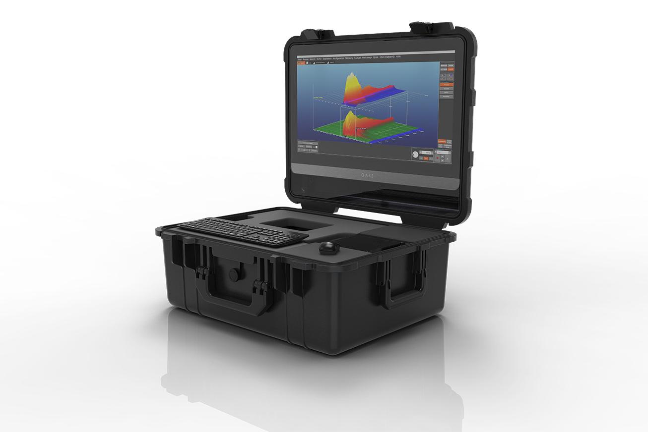
Upgrade now!
Optimizer4D takes your crack detection to a whole new level. With its powerful new features, you can save valuable resources and money!
Find out more now and request a non-binding offer.more information
Here we collect CiS.01 specific problem solutions and usage information, how to teach the sensor and how to deal with different error messages. If you do not find what you are looking for here, you can contact us by e-mail (info@qass.net) or by phone.
CiS.01 Error messages
This error message is displayed when the plug control signal fails to appear.
This fault can only occur if the plug control has been activated in the basic settings. In this case the CiS.01 expects a permanent 24V signal level at pin 23 of the input connector. If this signal is missing, this is equated with "not connected plug". In this case the CiS.01 can no longer receive a measurement activation.
- Check the input plug
- Check the plug control signal
This message appears when the press does not acknowledge that the crack detector has sent a crack or break message. This feature must be activated in the systems unit settings.
The straightening machine must activate a confirmation signal at pin 16 of the input connector after the CiS.01 has reported a crack or break. If this signal is not confirmed, the CiS.01 changes to the fault state with the next workpiece change signal.
Reset the unit by pressing any key on the keypad. If the unit will not reset check the signal from the PLC, repair as necessary.
Attention! A workpiece with crack indication not recognized by the straightening press may be located in the transport device!
The message occurs if the coupling value deviates from the specified range during the self-test. This can happen after a sensor has been converted, by loosening the fastening screw or by external influences such as contamination.
The coupling indicates how well the sensor and straightening press are connected to each other.
Before changing the limits of the pulse test, you should press "F1" and try to increase the sensor adjustment by checking the screw connection and removing any contamination.
If very small values (<0.1) are displayed when teaching the coupling value (teach pulse), it should be urgently checked whether the prerequisite for the reliable detection of a released sensor is given. For this purpose, the sensor must be released after teaching and the machine must be started. Now, after the first component, a corresponding error message (error coupling to port x) should appear.
When teaching the limit values of the channels and the sensors, there is always the danger of "making away" an error existing in the device. Therefore, work in this area should only be done with great caution and with sufficient expertise. In case of doubt there is always the possibility to contact the QASS service center.
This error occurs if during the self test communications fails.
- Check the connections between the controller an the pre-amp.
- Pressing “enter” on the keypad will reset the unit.
- If the unit will not reset conduct a detailed inspection of the pre-amplifier, the cable, and the cable connectors. Repair or replace as necessary.
The fault occurs when an error occurs during the test of a measuring channel.
If an error occurs during the test of a measuring channel, the measured values are displayed in the line of the channel concerned. This may indicate a defective preamplifier.
If you replace the preamplifier, it may be necessary to reteach the channel boundaries.
Press "Enter" to reset the device.
If the device cannot be reset, you must reteach the channel boundaries:
Log on the system by “Esc” “Esc” “F8” “F1” “Esc”
- “F5” Unit settings
- “F5” Channel Parameters
- “F2” Teach Limits
- “F1” Start
- “F2” Save
- “Esc”
- “Arrow Right” To advance to channel 2
- Repeat steps 3, 4, 5, 6
- “Arrow Right” To advance to channel 3
- Repeat steps 3, 4, 5, 6
- “Esc” Back
- “Esc” Back
- “F7” Errors
- “F3” Channel
- “Enter” New Test
If a value below 300 or above 399 is displayed when teaching the channel limits, this indicates a malfunction or a defect within the overall system and must be checked without fail.When teaching the limit values of the channels and the sensors, there is always the risk of "eliminating" an existing error in the device. Therefore, work in this area should only be done with great caution and with sufficient expertise. In case of doubt, there is always the possibility to contact the QASS service center.
This error is displayed if the measured capacity at one of the connected ports is too low.
- The port that failed is marked. Check for a poor connection, they should be only hand tight, a damaged sensor cable, or a damaged sensor.
- Pressing “enter” on the keypad will reset the unit.
- If the unit will not reset replace the sensor cable.
- If the unit still will not reset replace the sensor. For directions on replacing the sensor please see error “coupling factor error”.
CiS.01 - Teaching of the sensor
Sometimes, after a change of the bolting of the sensor, the alert “error in coupling” is shown. Before you change the threshold values, it’s absolutely necessary to increase sensor coupling by cleaning the sensor and it’s contact surface.
After that, bolt the sensor thoroughly and teach the thresholds. To do this, use the menu and choose F2, Teach Pulse:
Hit these keys:
- „ENTER“ to enter the main menu
- Key„F5“ (system settings)
- Key „F4“ (Port parameter)
- Key „F2“ (Teach Thresholds)
- Key „F1“ (Start)
- Key „F2“ (Save)
Repeat for every sensor that is mounted.
After that, hit “ESC” several times.