Zerstörungsfreie Härtemessung
Non-destructive hardness measurement, automated and reliable with the QASS measuring system
Non-destructive, contactless and in real time
With our µmagnetic measuring system, you can test the hardness of ferromagnetic materials in a non-contact and non-destructive manner. Real-time spectral analysis makes the properties of your material visible live. Components can be measured within 200 ms.
Customer and process specific solutions
QASS adapts the µmagnetic measuring system to fit your process and non- destructive hardness testing requirements ideally. If you need a special sensor design, we will develop it. If you need an individual handling system, we will set up the QOBOT perfectly for you.
100% instead of random testing
Our µmagnetic technology can be integrated into all process stages of manufacturing. Be it material or mix-up tests before the first manufacturing step or quality tests in or at the end of the manufacturing process.
Hardness testing Pre-, In- and Post-Process
All applications of QASS µmagnetic are possible upstream, in-process and downstream of the finished component. Inspect your objects and material non-destructively and contact-free. The implementation in the process depends on the available space and the process control.
Non-destructive hardness testing with QASS
QASS µmagnetic replaces time-consuming, destructive hardness testing with a non-contact, user-friendly inline process.
Our process is robust, suitable for industrial use, and designed for 24/7 operation. Measurement times of less than one second and real-time data processing allow the system to make immediate decisions with a direct connection to the machine control system, for example, for component ejection or process optimization.
The 100% inspection allows process irregularities and gradual changes to be detected at an early stage. This enables you to react in good time – and avoid rejects.
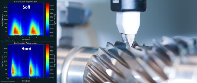
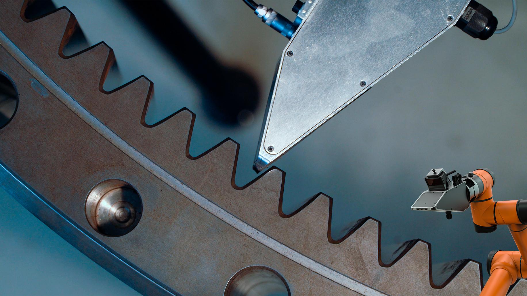
Figure 1: Guided QASS sensors determine the surface hardness of a gear flank completely contact-free and non-destructively.
Any Geometry
Whether shafts, gears, or complex shapes—thanks to their modular sensor nose, QASS µmagnetic sensors measure the hardness of a wide variety of component geometries.
Measurements up to 400°C
Our water-cooled sensors reliably measure hardness values even on hot workpieces with temperatures up to 400 °C.
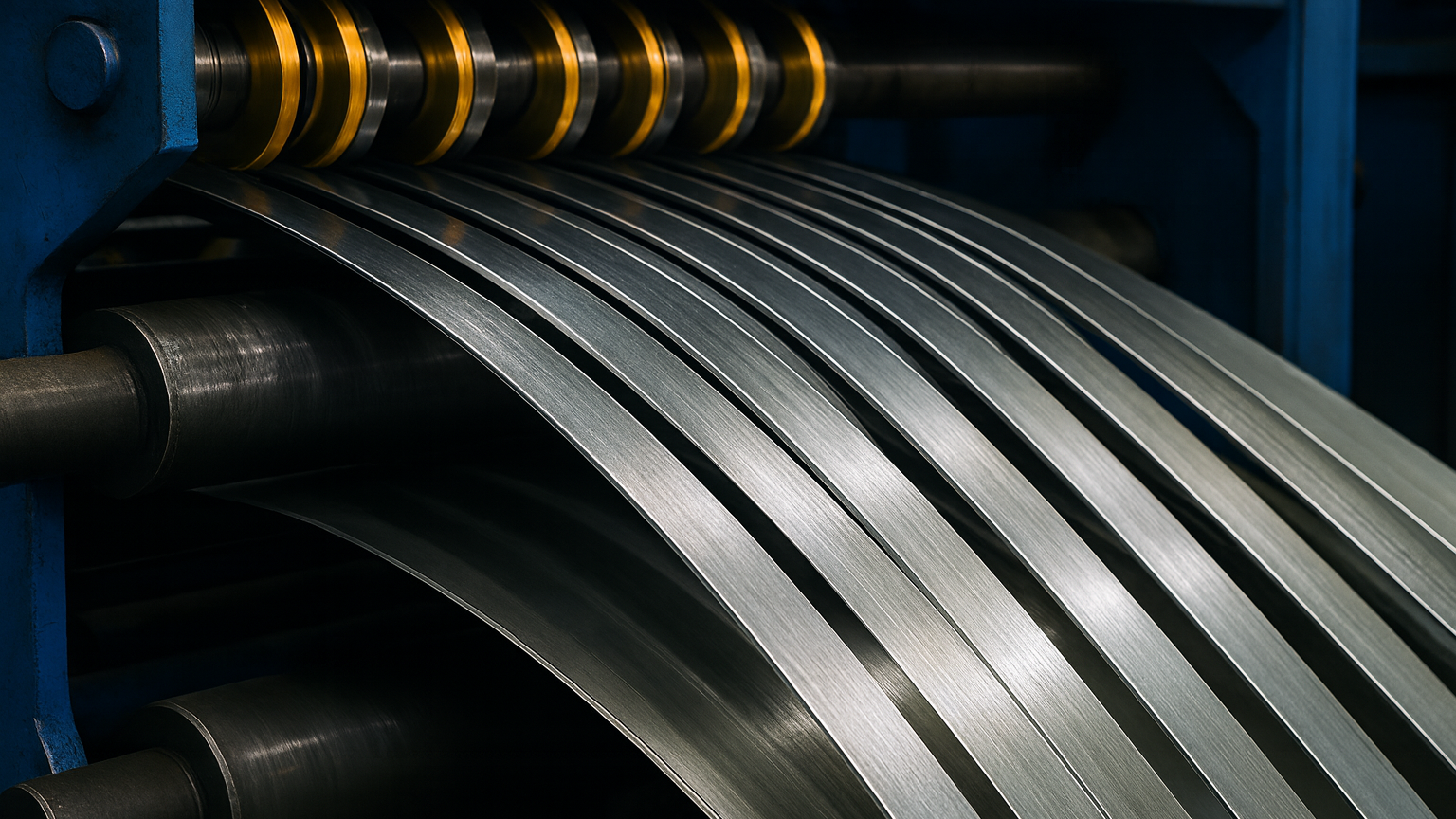
Inline in Bewegung
A measurement takes only 200 ms—perfect for rotating rollers, strip steel, or measurements directly in the machine. QASS µmagnetic sensors measure component hardness even in motion.
Grinding burn detection
QASS µmagnetic immediately detects structural changes such as grinding burn. Early detection during the process prevents rejects, ensures quality standards, and reduces rework costs.
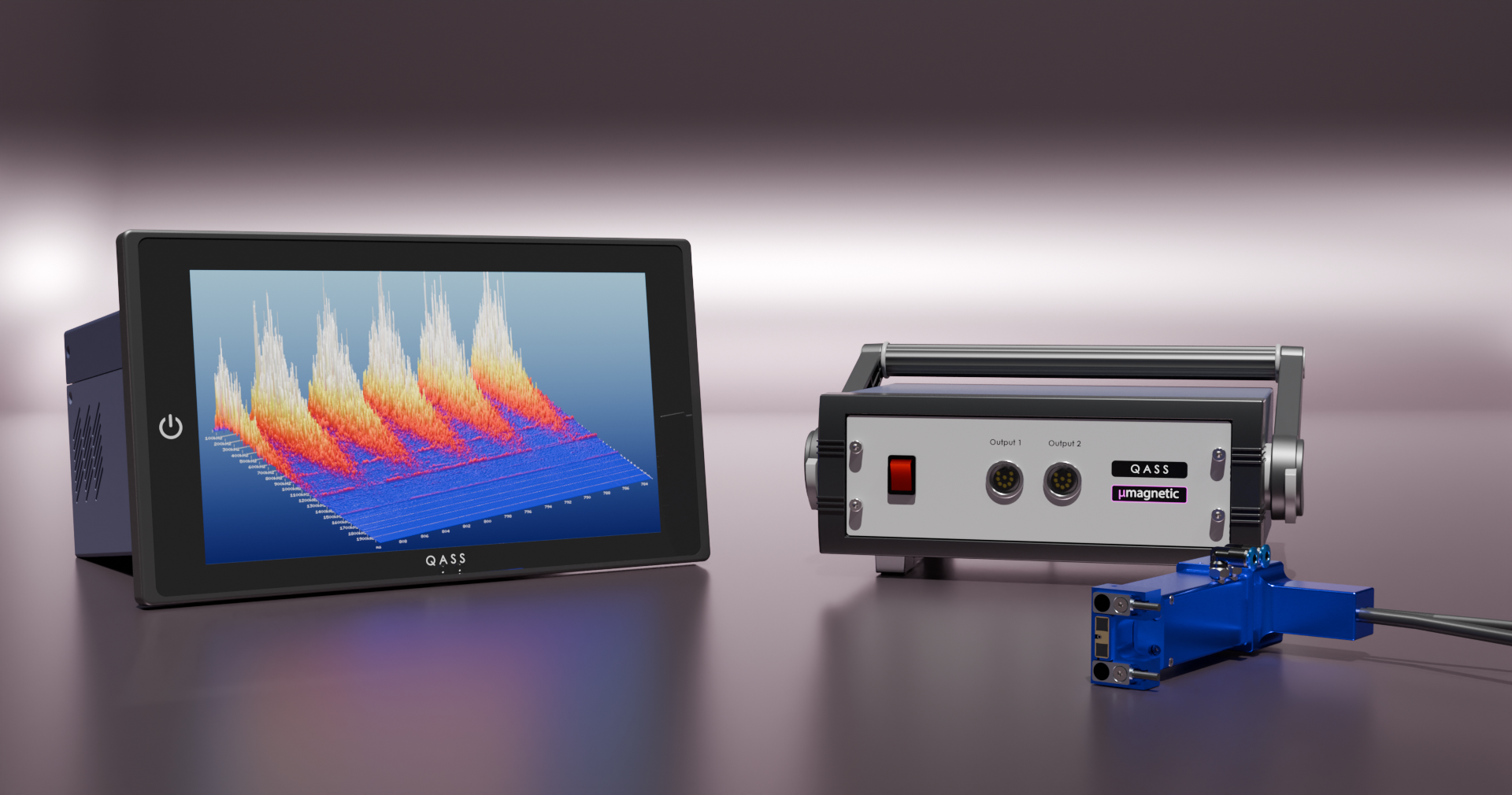
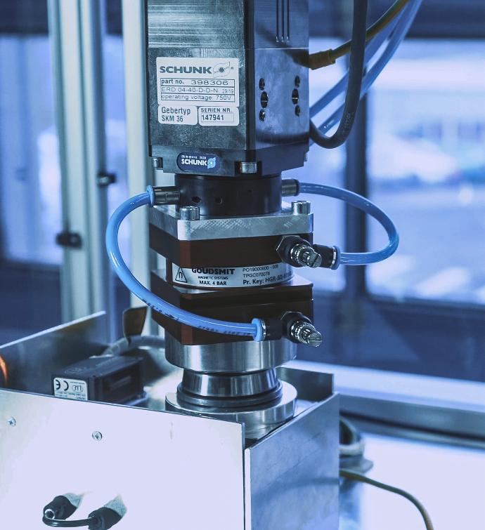
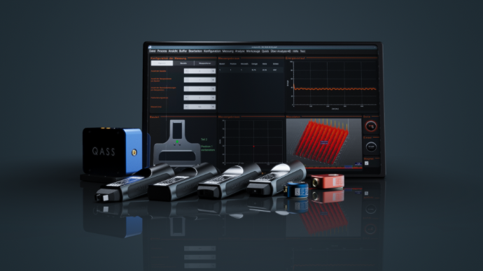
Figure 2: QASS µmagnetic measuring chain: Consisting of the Optimizer4D measuring system (left), a power amplifier (center), and a modular µmagnetic sensor (right).
The physical principle: the magnetic Barkhausen effect
Ferromagnetic materials consist of many Weiss domains. Without an external magnetic field, they are randomly oriented and cancel each other out. As the field strength increases, the domains begin to align themselves along the field lines. Crucially, a domain flips abruptly as a unit – each of these switches results in a change in the magnetic flux. This generates current pulses in a measuring coil: Barkhausen noise.
Mechanical hardness correlates directly with the defect density (vacancies, foreign atoms, interstitial atoms, dislocations) in the crystal grid, which in turn determines magnetic hardness. Materials with high mechanical hardness are therefore also magnetically hard.
In martensite, for example, the carbon is forcibly dissolved in interstitial lattice sites, which significantly increases the defect density. In ferrite or pearlite, on the other hand, the carbon has precipitated as carbide at grain boundaries. This fundamental relationship forms the basis for non-destructive hardness measurement using Barkhausen noise analysis.
This is how QASS µmagnetic works
An electromagnet inside the µmagnetic sensors generates a periodic alternating field with a defined frequency. This is induced into the component to be measured via an air gap (<1 mm). A receiver coil (ferrite antenna) then detects the resulting changes in magnetic flux. The resulting time-amplitude signal is recorded, sent to the measuring system in real time, and digitally processed.
The difference to conventional systems: QASS performs a FFT (Fast Fourier Transformation) on the signal in real time. This produces a time-amplitude-frequency signal that enables frequency-selective analysis and frequency filtering. This new signal is displayed in a 3D spectral landscape. Industrial interference caused by frequency converters or servo motors, for example, is reliably detected and effectively filtered out.
When comparing hard materials with less hard materials, differences become apparent in this 3D landscape: hard materials show weaker, less intense signals, while less hard materials show correspondingly more intense signals (see Fig. 4).
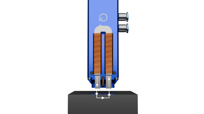 Figure 3: QASS sensors determine surface hardness completely contact-free and non-destructively with an air gap of 0.3 – 0.7 mm.
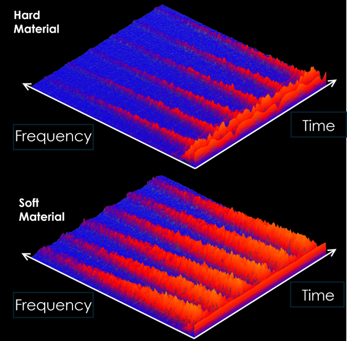 Figure 4: Comparison of hard material vs. soft material in the QASS 3D spectral landscape.
Spectral image: Hard and soft (magnetic) material
The software produces such a spectral process image.
Hard magnetic materials exhibit weak Barkhausen signals and are also mechanically hard.
Soft magnetic materials are easily magnetized, exhibit strong signals, and are also mechanically soft.
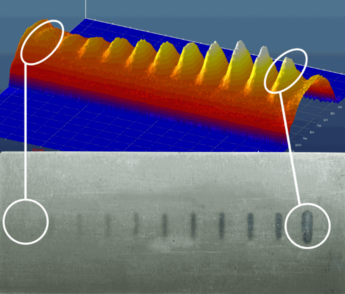
Detection of induction zones
Our high-resolution analysis enables the precise detection of thermally affected areas—known as tempering zones—directly on the workpiece surface. In the example shown, a steel test specimen (Nital etching specimen) was deliberately provided with tempering zones. The subsequent 3D evaluation visualizes the magnetic changes along the test specimen.
The clearly defined signal peaks in the diagram correspond exactly to the zones introduced and impressively demonstrate the sensitivity and accuracy of QASS measurement technology. This allows structural changes to be detected reliably and non-destructively – ideal for process control after hardening and grinding processes.
Calibration & measurement accuracy
QASS µmagnetic hardness measurement is a comparative measurement and requires calibration.
Factors to be taken into account during calibration:
- Residual stresses (created/broken down by heat treatment)
- Structural differences (grain size, carbide distribution)
- Distance (constant or known, otherwise distorted)
- Geometry (Wall thickness, curvature, edge effects)
- Surface condition (roughness/contamination irrelevant, except for ferromagnetic particles)
A function for the mostly linear relationship between hardness and measured energy is calculated from the calibration data. The measurement can be repeated as often as desired, offers high reproducibility even with measurement times < 1 s, and achieves a conversion accuracy of ± 1 HRC with careful calibration.
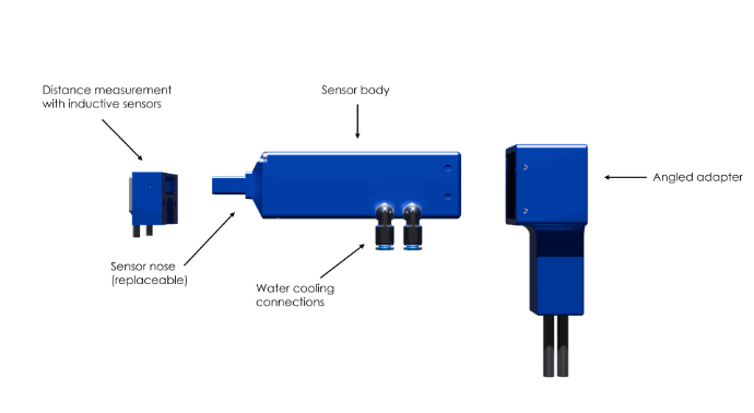
Sensors and integration into the line
- Modular sensor with interchangeable sensor head for different geometries, e.g., gear teeth, flat surfaces, shafts.
- Active cooling: Use up to 500 °C.
- Measurement in motion: up to 600 mm/s – ideal for detecting hardness gradients and anomalies (e.g., soft spots) in moving components.
- Distance management: During measurement, the distance is kept constant or recorded; optional inductive distance sensors compensate for the influence of distance on the measured value.
- Interfaces: IO connections, Profinet, LAN, WLAN for effective machine communication.
- Robust data processing: Spectral analysis combined with machine learning methods for detecting and suppressing electromagnetic interference.
- Suitable for 24/7 operation: Designed for continuous industrial use.
Software & Operation
We provide a customer- and application-specific user interface for each system.
A rights management system protects functions from unauthorized access. Signal devices, monitors, and displays can be controlled via standard interfaces. All QASS systems are equipped for remote support, allowing many issues to be resolved without on-site intervention.
Früherkennung von Weichfleckigkeit direkt im Richtprozess
In modernen Getriebefertigungs- und Richtanlagen ist die Vermeidung von lokal begrenzten Härteminderungen („Weichfleckigkeit“) an gehärteten Wellen ein entscheidender Qualitätsfaktor. Mit QASS µmagnetic können diese Fehler frühzeitig also direkt während des Richtvorgangs erkannt werden.
Warum ist das wichtig?
- Weichfleckigkeit führt zu lokal reduzierter Härte auf der Wellenoberfläche oder im Randbereich und kann damit die Lebensdauer sowie die Funktionssicherheit von Getriebewellen deutlich beeinträchtigen.
- Häufige Ursachen wie z. B. ungleichmäßige Wärmebehandlung, lokale Entkohlung, unzureichende Abschreckung oder oberflächenbedingte Fehler, lassen sich nicht zuverlässig mit herkömmlichen Sicht- oder Inline-Kontrollen erkennen.
- Durch die Integration der Härtemessung während des Richtens lassen sich solche Fehler bereits im Herstellprozess auffinden, sodass eine Nacharbeit oder Aussortierung direkt erfolgen kann und kostenintensive Ausfälle oder Rückrufe vermieden werden können.

Vorteile für Ihre Produktion
-
Schnelle Rückmeldung: Weichfleckigkeit wird früh erkannt, ohne dass komplette Härteprüfungen oder makrografische Nachweise nötig sind.
-
Prozesssicherheit steigern: Durch Inline-Härtemessung wird Ihre Fertigungskette zuverlässiger und mögliche Weichfleckigkeit nicht erst im Endprüfprozess erkannt.
-
Kostenreduzierung: Reduzierter Ausschuss, geringerer Nacharbeitsaufwand, weniger Reklamationen.
-
Datenintegration: Messergebnisse können in Ihr MES/Logging-System überführt werden, wodurch Trendanalysen möglich sind und prozessbegleitende Verbesserungen einfacher werden.
Typischer Ablauf in der Anwendung
-
Die Getriebewelle wird während des Richtens in der Anlage vermessen.
-
QASS µmagnetic führt eine schnelle Messung an definierten Positionen durch (z. B. entlang der gehärteten Laufbahn, Übergänge und Endbereiche).
-
Automatische Auswertung: Härteverlauf wird angezeigt, Auffälligkeiten („weiche Zonen“) werden markiert und protokolliert.
-
Bei Überschreitung definierter Schwellenwerte erfolgt eine Kennzeichnung bzw. automatische Aussonderung oder Weiterleitung zur Fehlerbearbeitung.
-
Alle Messdaten werden mit Zeitstempel, Wellen‐ID, Messpositionierung und ggf. Richtmaschinenparametern verknüpft – für Rückverfolgbarkeit und Qualitätssicherung.
Practical examples of non-destructive hardness testing with QASS
An autonomous testing station was developed for a manufacturer of low-wear castings. An industrial robot picks up a casting from a bulk container (bin picking) and transports it to
a QASS µmagnetic hardness testing device. The casting is then visually inspected for casting defects, weighed, and sorted according to weight.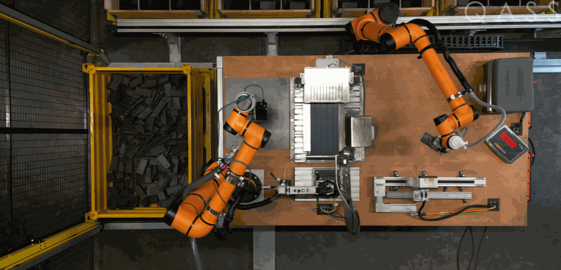
In cooperation with a steel strip manufacturer, a hardness testing system was developed that performs continuous hardness measurements every second on a steel strip passing under the sensor at a speed of up to 20 m/min.
The measuring system operates fully automatically 24/7, features obstacle detection, and uses machine learning methods for automatic calibration to new steel grades. This documents a seamless hardness profile over several kilometers of strip length.
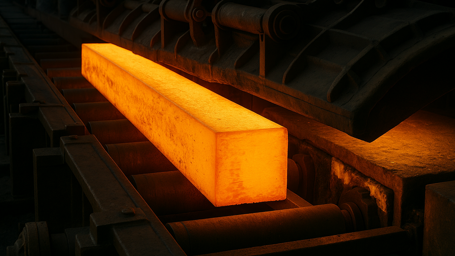
During press hardening, the warm sheet metal is cooled more quickly in certain areas than in others during a deep drawing process due to cooling channels in the deep drawing tool.
This method is particularly effective for achieving hardness gradients in car body parts. To determine the success of the press hardening process, the material is measured at a temperature of 400°C. To do this, the contact time is kept short and the sensor is actively cooled with water.
Rollers undergo cold work hardening during rolling. It is therefore necessary to grind them down at regular intervals to remove the hardened areas. The end point of the reworking process is usually determined based on experience and visual inspection. In doing so, more material is often removed than necessary to ensure that all imperfections have been eliminated. In some cases, aids such as the minimally invasive rebound method according to Leeb are used, which only provide selective information about the hardness of the roll.
Even these smallest indentations must be removed by further grinding. With 100% hardness monitoring using Barkhausen noise, grinding away the indentations is no longer necessary and removal is limited to the actual damage.
Grinding burn is thermal damage to the component surface caused by improper process control. The heat input leads to local changes in residual stress, possibly to a decrease in hardness and, in the worst case, to the formation of a new hardness zone of nanocrystalline, glass-hard martensite on the component surface. Grinding burn, especially when it is only slight, is difficult or impossible to detect visually. The classic method for examining components for grinding burn is nital etching. This wet chemical process is time-consuming and involves the use of aggressive chemicals such as nitric acid.
In close cooperation with a manufacturer of planetary gears for wind turbines, a robot-assisted process was developed to inspect ring gears for grinding burn. The following shows a sensor optimized for this application just above the surface of a tooth flank, which is scanned line by line without contact. 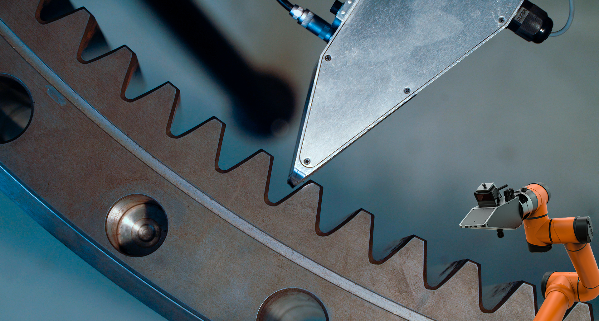
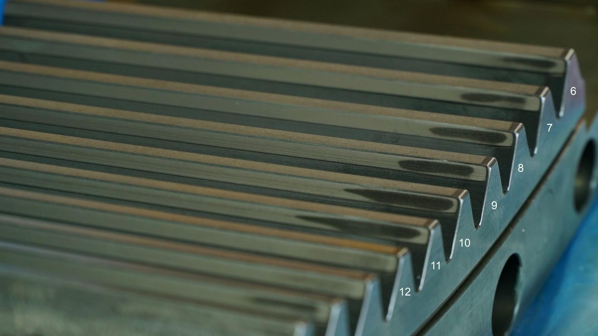
The company imq in Crimmitschau (Saxony) manufactures Nital etching blocks that are used to determine the quality of Nital etching baths. The steel block, measuring approximately 60 mm x 20 mm x 8 mm, contains eleven tempering and new hardening zones that have been artificially created using a laser. The image was created by scanning the block line by line: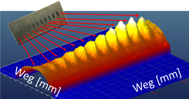
The segmentally induction-hardened shaft shown in Figure 7 must be fed into the machine in the correct position for further processing. Measuring the shaft along its longitudinal axis produces the graph shown in Figure 7 below. This information is used to feed the shaft into the machine in the correct position.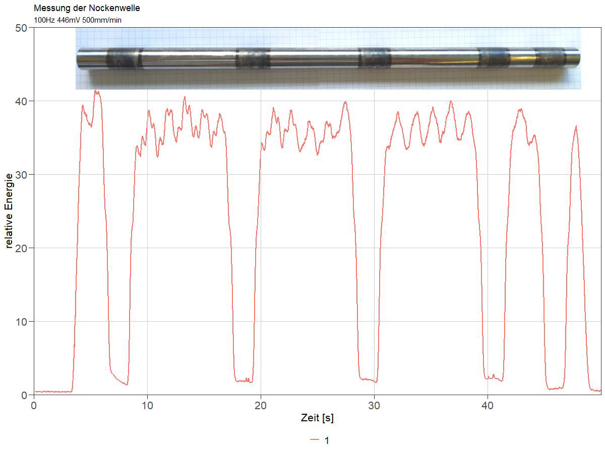
Why QASS µmagnetic?
All advantages at a glance
Non-contact & non-destructive
100% inspection instead of random sampling.
Real-time decisions
Measurement < 1s, direct control of the system.
Industrial robust
24/7 operation, heat resistant up to 500 °C, component movement up to 600 mm/s.
Geometrically flexible
Sensor tips for gear teeth, flat surfaces, shafts.
Clear signals
FFT-based, frequency-selective, ML-supported against EM interference.
High accuracy
± 1 HRC (with careful calibration)
Schedule a consultation now!
Contact our experts for non-binding information about the possibilities for your industrial processes.
Mikromagnetic as a system solution
Handling systems & complete systems
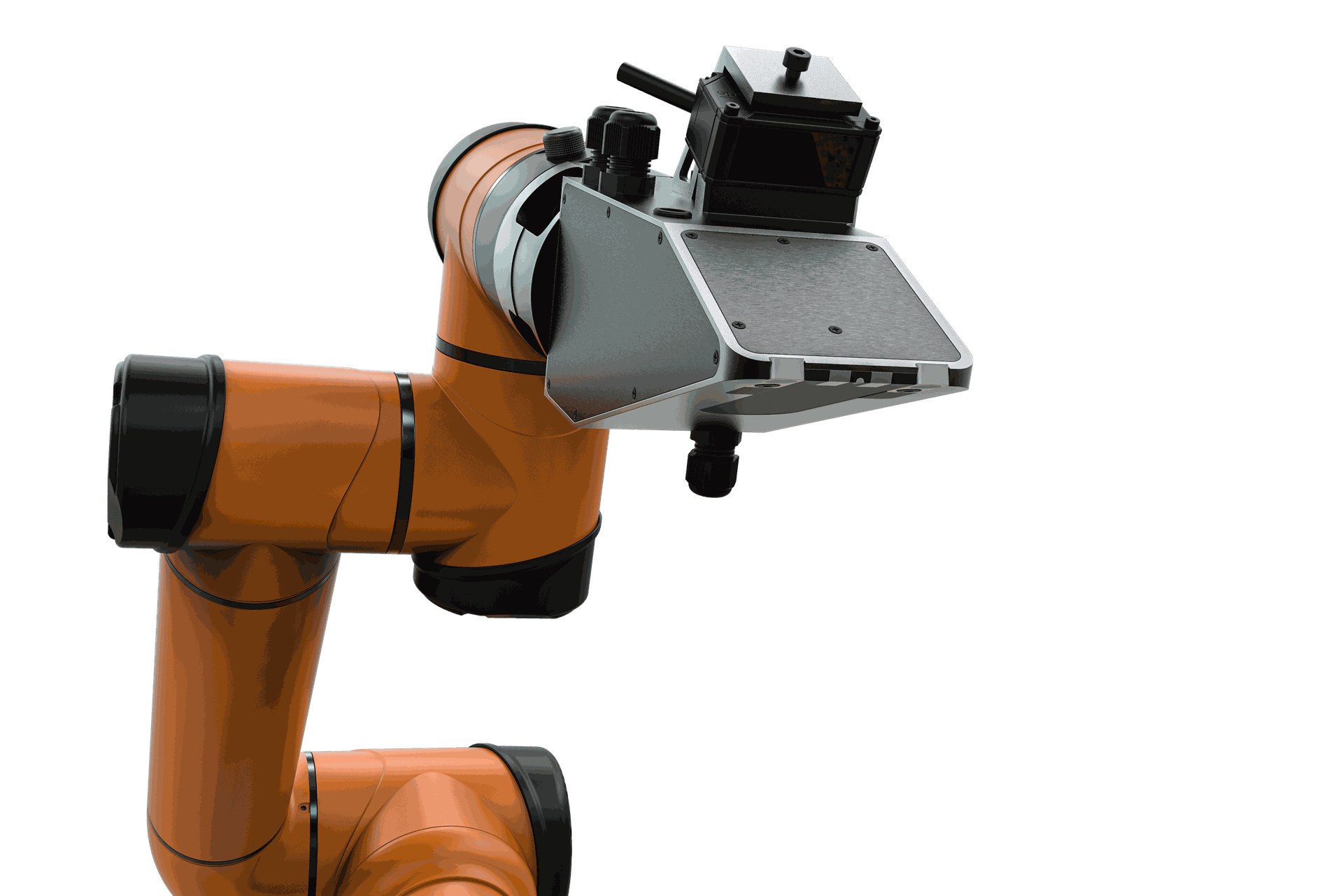
Modern handling and sensor guidance by QOBOT
The QOBOT handling system is based on an intelligent combination of sensor technology and robotics. It was developed by QASS specifically for the µmagnetic-technology and can be purchased together with it as a system solution.
The QOBOT is individually adapted by QASS to the process and the production environment. The system can be used pre-, in-, and post-process. The AUBO-i5 Co-Bot built into the handling system is flexible in use and, thanks to its range of motion of 924 mm**, enables hardness measurement of components of different geometries and lengths. A laser distance sensor detects the robot path so that the µmagnetic sensor is correctly positioned during measurement. The control of the sensor technology and robotics installed in the QOBOT is integrated with the µmagnetic measuring system.
Explaining Zelos
The Zelos system was developed by QASS with the aim of supporting companies in quality assurance during sintering. The Zelos system is an automated laboratory system for testing the homogeneity of powder metallurgical green compacts homogeneity of powder metallurgical green compacts. The measuring system installed in the plant is the QASS Optimizer4D with µmagnetic – the micro-magnetic extension for hardness testing, Grinding burn detection and homogeneity testing of green compacts.
The Zelos system for testing the homogeneity of powder metallurgical green compacts combines micromagnetic measurement technology with gentle component handling. Test specimens are gently removed from the holder using a pneumatically controlled magnetic gripper and guided to the micromagnetic sensor via two linear axes. A laser distance sensor ensures that the test specimen is positioned correctly.