Wire drawing processes
Real-time monitoring, preventive defect avoidance and control of the wire drawing process
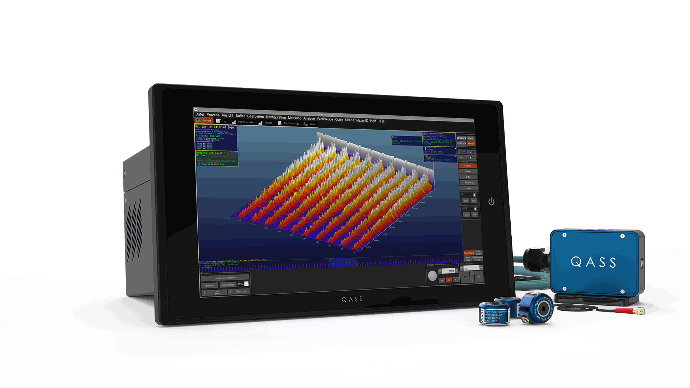
In-line measurement system
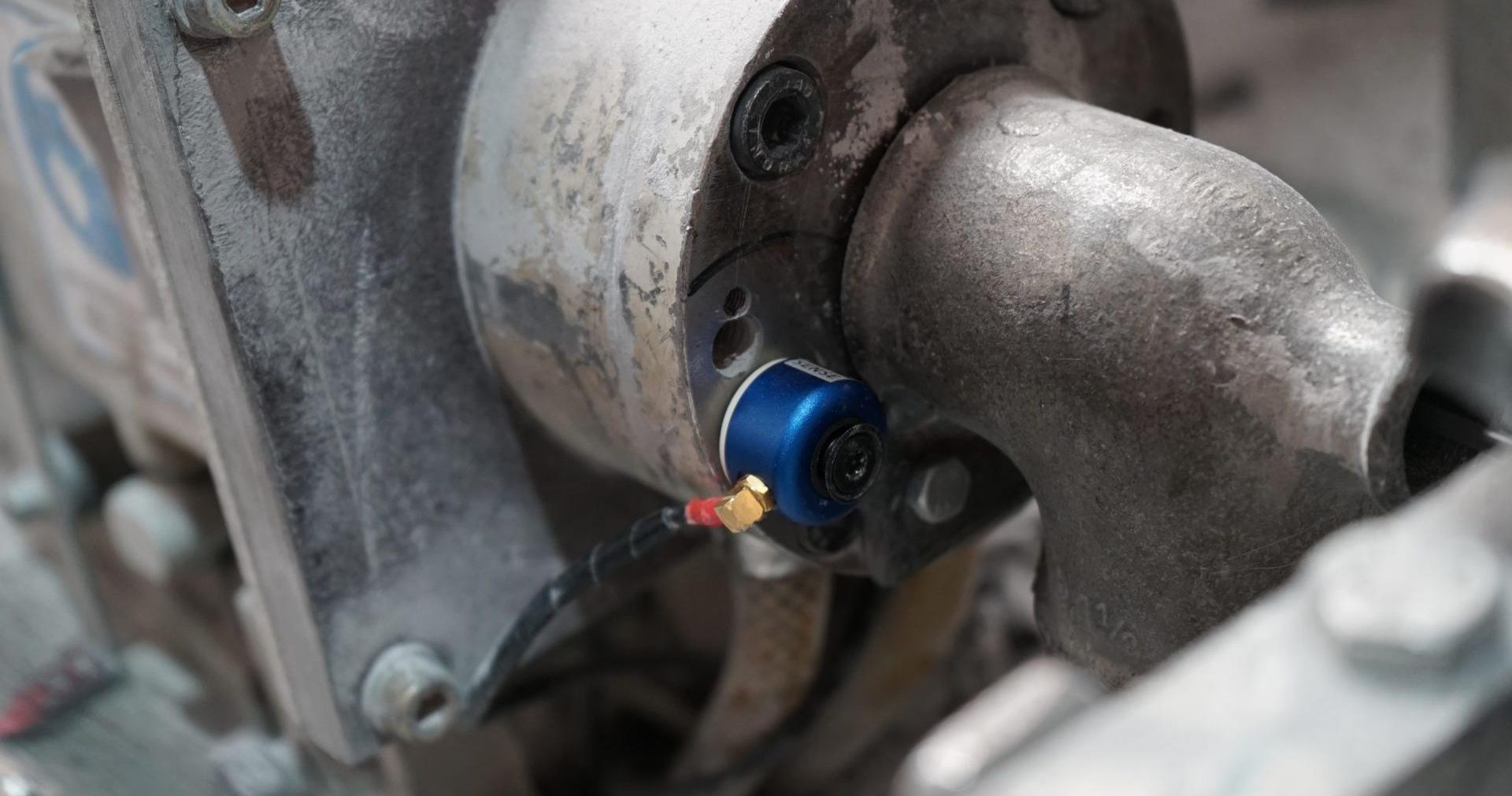
The permanent and force-locked connection of the QASS structure-borne sound sensor to the machine, enables the Optimizer4D to seamlessly monitor your wire drawing process. The data is processed and evaluated in real time.
Preventive error avoidance
The data obtained from our sensors goes through spectral processing using Fourier transformation, as well as noise suppression with adaptive filters and pattern recognition. This allows the smallest deviations in the process to be detected and production errors to be avoided.
Automatic determination of the drawing speed
With the Optimizer4D, the optimum drawing speed does not have to be laboriously tested. The measuring system uses the sensor data obtained to calculate the speed which, in conjunction with cross-section reduction and lubrication, delivers the best possible quality.
Easy Implementation
Our measuring system can be easily installed on your machine by our service staff without interrupting the running process. The structure-borne sound sensor is suitable for almost every wire drawing machine.
Complete quality documentation for your wire
Anyone who produces wire of a particularly high quality knows that the error tolerances are very small. The Optimizer4D helps to determine the optimum drawing speed. At the same time, the system detects when the loss of lubricant is imminent or has already occurred, and can stop the line if desired. Temporary mechanical damage, such as wire breaks, is reflected in the HFIM image. The Optimizer4D not only monitors production, but also documents the results. The software provides information on the extent to which the quality deviates from the deviates from the desired standards. QASS enables the following features:
- An automated monitoring and documentation of all wire draws;
- Real-time visualizations of the running process, including in a 3D landscape;
- Deviations are immediately detected and documented;
- Error logging, even of small sections containing errors;
- Quality certificate with ring number and time stamp;
- A graph shows the quality of each coil, each ring. If desired, the graph can be output as a document..
Easy implementation for existing processes
What makes implementation so straightforward?
- No interruption of the running process
- Simple sensor installation
- Only one-time employee training required
- On-site consultation and installation by QASS
- Practical performance tools for machine operators
- The QASS Service Promise
Optimizer4D - The measuring system for wire drawing
Condition monitoring of a drawing die sequence
Avoiding surface defects such as draw marks is more important than detecting surface defects because avoiding defects helps improve the quality of the end product and reduces the cost of repairs or scrap. When surface defects are avoided, the need for inspection and rework is reduced, saving time and resources.
This is where QASS Condition Monitoring comes in. The Optimizer4D brings transparency by monitoring the condition of a drawing die sequence. In a dry drawing line, the cross-section reduction of a steel wire is monitored with piezoelectric sensors. After each drawing stage, the wire hardens and the friction behavior changes. The drawing tool and lubricant supply must be adjusted. In the ideal lubrication condition, mixed friction prevails, which is acoustically different from static or liquid friction. Changes in friction between the drawing die and the wire surface are continuously visualized to avoid critical friction. The drawing die transmits stronger signals as wear increases. The sum of critical friction powers causes frequency deviations. When tribological conditions change critically, the HFIM signal image also changes significantly. Optimizer4D detects this difference in system friction automatically and autonomously.

Determination of the optimum drawing speed
Different drawing speeds provide different HFIM signals. If the quality of the product deteriorates, easily detectable anomalies appear in the HFIM image. The QASS measurement system can optimize your processes and determine the most economical and optimal drawing speed.
 An alternative view made possible by the QASS measurement system. It is particularly suitable for verifying the most economical production speed (DoE).
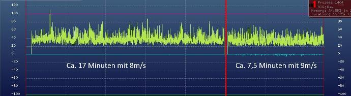
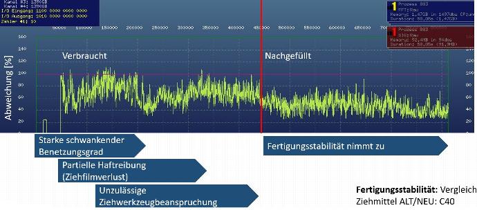
Fig. left: Determination of the optimum drawing speed. Speed increase from 8 m/s to 9 m/s. Working card 8 m/s (+/- 1 m/s). Material: cold heading steel.
Result: Higher drawing speed while maintaining the same quality. An increase from 8 m/s to 9 m/s is recommended. Friction ratios and degree of wetting show equally stable conditions.
Another example to verify the optimal drawing speed.
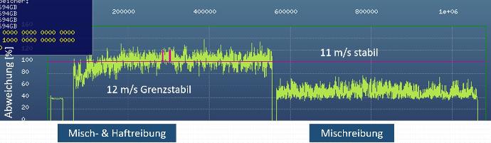
Fig. left: Determination of the optimum drawing speed. Specification of the work order: 11 m/s (+/-1 m/s). Mixed friction and static friction occur in the left-hand range of 12 m/s. In the right-hand area, drawing takes place at a speed of 11 m/s. Only mixed friction occurs here.
Result after analysis: The optimum drawing speed for consistent quality is 11.8 m/s.
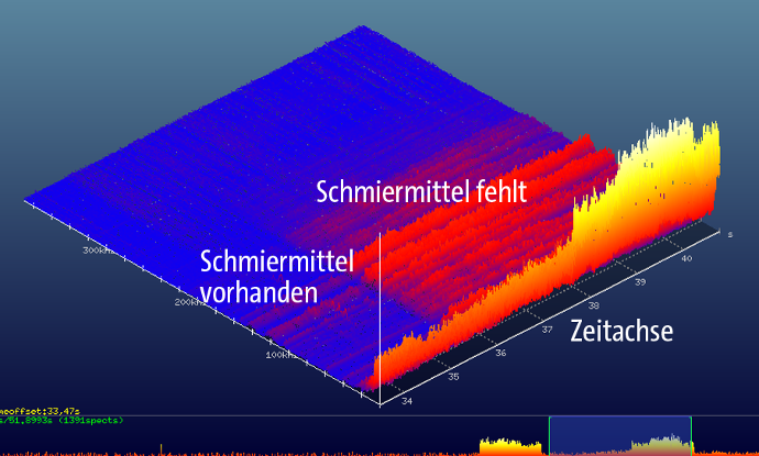
A brand new die emits different HFIM signals than a worn one. Optimizer4D detects in real time when the determined tolerance limits are exceeded. To do this, the measuring system is given information about the drawing die run card and the production order. Optimizer4D checks the quality on the last two static drawing dies of a multiple wire drawing line - after which automatic quality monitoring of your process is ensured. Among other things, this checks the quality of the drawing medium. Right picture: a lubricant film breakage detected by QASS on a multiple wire drawing line.
Production stability: comparison between old and new drawing agent (C40).
Draw comparison: V40C vs. C450.
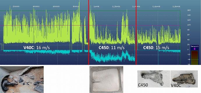
Sequence: Start at 16 m/s with V40C. Strong draw residues on the wire and strong draw solidifications (approx. 10 cm long) in the draw box. The change to C450 caused smaller drawing agent solidifications and slightly better, constant contact friction.
Result: Both drawing agents are unsuitable. However, C450 tends more to mixed friction; less tunneling; clumping.
Cooperation with Netzwerk Draht
“With most current measurement methods, you learn about quality defects in the finished material. From production, "a piece of wire" comes to the laboratory and if the quality does not fit, it is interesting but too late. Methods are sought and tested that provide information about the quality during the production process.
A method based on structure-borne sound measurements is being tested in the region, together with QASS GmbH, which offers solutions in this area.”
Source : Netzwerk Draht Homepage .
Only QASS can do that
There are many measuring instruments for acoustic quality control, but only QASS analyzes frequencies in addition to signal strength. Only the selective frequency display opens up a differentiated view of the process.
Certain frequency ranges carry different information than others - the QASS way makes it easy to mask out the ranges that contain, for example, interference or signals from irrelevant sources. In addition, the QASS system is less sensitive to dirt than, for example, optical-based methods.
Acoustic testing is also less prone to misinterpretation of the surface. Even internal damage can be detected if it produces stronger emissions than an undamaged wire during plastic deformation from die to die.
Arrange a consultation appointment now!
Ask our experts aboput the possibilities for your industrial processes without obligation.